- 您现在的位置:买卖IC网 > Sheet目录100 > NHD-12232AZ-FSW-GBW (Newhaven Display Intl)LCD MOD GRAPH 122X32 WH TRANSFL
[4]
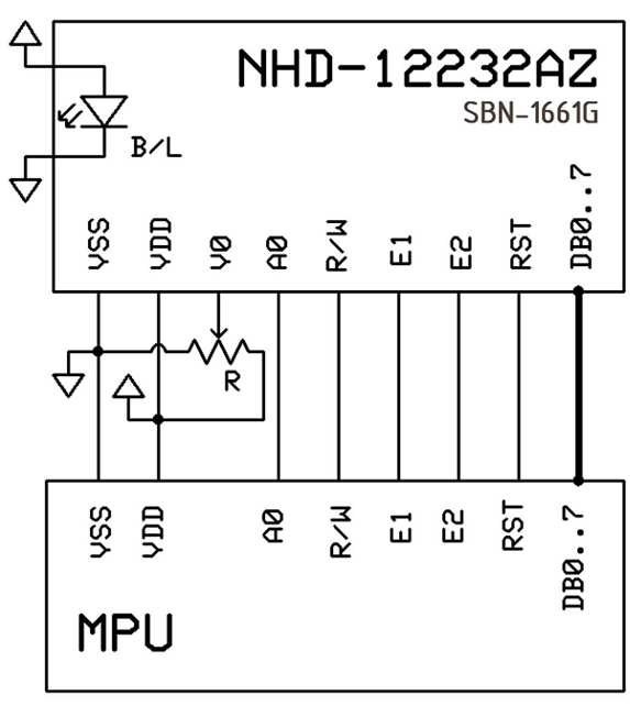
Pin Description and Wiring Diagram
Pin No.
Symbol
External
Connection
Function Description
1 VSS Power Supply Ground
2 VDD Power Supply Power supply for logic (+5.0V)
3 V0 Adj Power Supply Power supply for contrast (approx. 0.5V)
4 RST MPU Active LOW Reset signal
5 E1 MPU Operation enable signal. Falling edge triggered, SEG (1~60)
6 E2 MPU Operation enable signal. Falling edge triggered, SEG (61~120)
7 R/W MPU Read/Write select signal, R/W=1: Read R/W: =0: Write
8 A0 MPU Register select signal. A0=0: Command, A0=1: Data
9-16 DB0-DB7 MPU This is an 8-bit bi-directional data bus
17 LED+ Power Supply Power supply for LED Backlight (+5.0V via on-board resistor)
18 LED- Power Supply Ground for Backlight
Recommended LCD connector:
2.54mm pitch pins
Backlight connector:
-
Mates with
: -

发布紧急采购,3分钟左右您将得到回复。
相关PDF资料
NHD-12232DZ-FSPG-GBW
LCD MOD GRAPH 122X32 GRN TRANSFL
NHD-12232DZ-FSW-GBW
LCD MOD GRAPH 122X32 WH TRANSFL
NHD-12232DZ-FSY-GBW
LCD MOD GRAPH 122X32 Y/G TRANSFL
NHD-12232DZ-NSW-BBW
LCD MOD GRAPH 122X32 WH TRANSM
NHD-12232KZ-NSW-BBW-P
LCD MOD GRAPH 122X32 WH TRANSM
NHD-12232WG-EYYH-V#A
LCD MOD GRAPH 122X32 Y/G TRANSFL
NHD-12864AZ-FL-GBW
LCD MOD GRAPH 128X64 Y/G TRANSFL
NHD-12864AZ-FL-YBW
LCD MOD GRAPH 128X64 Y/G TRANSFL
相关代理商/技术参数
NHD-12232DZ-FSPG-GBW
功能描述:LCD 图形显示模块和配件 STN-Gray Transfl 65.8 x 27.2 RoHS:否 制造商:ELECTRONIC ASSEMBLY 产品: 分辨率:128 x 64 流体类型:FSTN Positive 接口: 背光: 背景色:White 工作温度范围:- 20 C to + 70 C 封装:Bulk
NHD-12232DZ-FSPG-YBW
功能描述:LCD 图形显示模块和配件 STN-Y/G Transfl 65.8 x 27.2 RoHS:否 制造商:ELECTRONIC ASSEMBLY 产品: 分辨率:128 x 64 流体类型:FSTN Positive 接口: 背光: 背景色:White 工作温度范围:- 20 C to + 70 C 封装:Bulk
NHD-12232DZ-FSW-GBW
功能描述:LCD 图形显示模块和配件 120 x 32 STN-GRAY 65.8 x 27.2 RoHS:否 制造商:ELECTRONIC ASSEMBLY 产品: 分辨率:128 x 64 流体类型:FSTN Positive 接口: 背光: 背景色:White 工作温度范围:- 20 C to + 70 C 封装:Bulk
NHD-12232DZ-FSY-GBW
功能描述:LCD 图形显示模块和配件 STN Gray Tranfl 65.8 x 27.2 RoHS:否 制造商:ELECTRONIC ASSEMBLY 产品: 分辨率:128 x 64 流体类型:FSTN Positive 接口: 背光: 背景色:White 工作温度范围:- 20 C to + 70 C 封装:Bulk
NHD-12232DZ-NSW-BBW
功能描述:LCD 图形显示模块和配件 120 x 32 STN-BLUE(-) 65.8 x 27.2 RoHS:否 制造商:ELECTRONIC ASSEMBLY 产品: 分辨率:128 x 64 流体类型:FSTN Positive 接口: 背光: 背景色:White 工作温度范围:- 20 C to + 70 C 封装:Bulk
NHD-12232KZ-NSW-BBW-P
功能描述:LCD 图形显示模块和配件 120 x 32 STN-BL (-) 83.5 x 27.5 RoHS:否 制造商:ELECTRONIC ASSEMBLY 产品: 分辨率:128 x 64 流体类型:FSTN Positive 接口: 背光: 背景色:White 工作温度范围:- 20 C to + 70 C 封装:Bulk
NHD-12232WG-EYYH-V#A
功能描述:LCD 图形显示模块和配件 120 x 32 STN-Y/G 80.0 x 36.0 RoHS:否 制造商:ELECTRONIC ASSEMBLY 产品: 分辨率:128 x 64 流体类型:FSTN Positive 接口: 背光: 背景色:White 工作温度范围:- 20 C to + 70 C 封装:Bulk
NHD-12864AZ-FL-GBW
功能描述:LCD 图形显示模块和配件 128 x 64 STN-GRAY 93.0 x 70.0 RoHS:否 制造商:ELECTRONIC ASSEMBLY 产品: 分辨率:128 x 64 流体类型:FSTN Positive 接口: 背光: 背景色:White 工作温度范围:- 20 C to + 70 C 封装:Bulk
